Electronics 101
a school kit that obeys Kirchhoff
 ▶ Click to start — full screen
Every school electronics set makes the same promise: snap a battery, a switch and a lamp together and the lamp lights. What the plastic parts never show is why — why two bulbs in series glow dim while the same two in parallel blaze, why a resistor tames an LED, why one careless wire from plus to minus is a short. This lab puts the kit on a 3D pegboard and runs a real circuit solver underneath it: you take parts out of the palette, wire terminals by clicking two gold pads, flip the switch, and every LED, bulb and meter answers with the number Kirchhoff’s laws demand. The board is a toy; the physics is not.
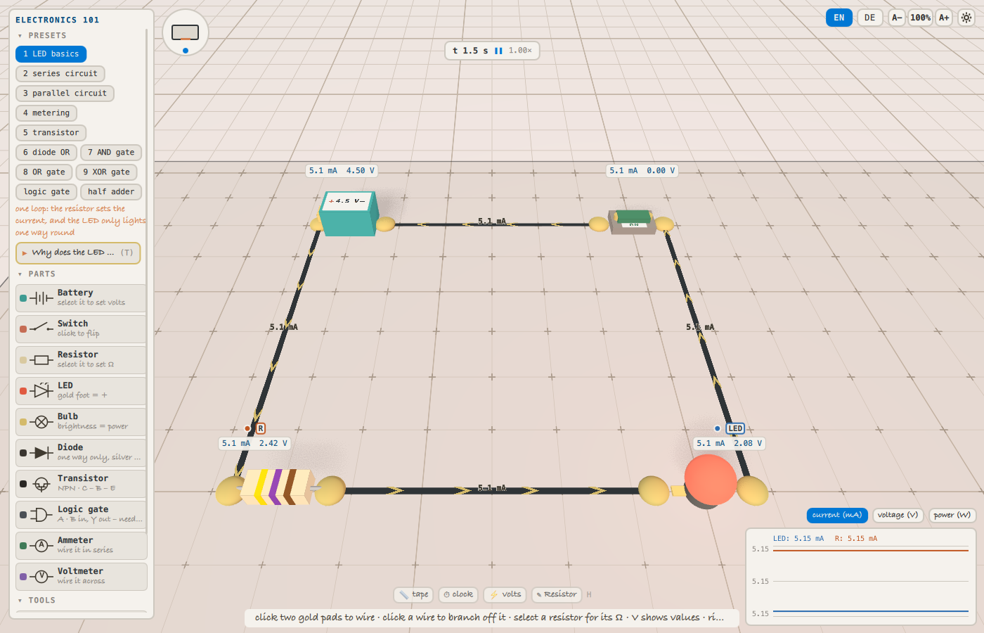
The whole argument in one picture: a 4.5 V cell, a 470 Ω resistor and an LED in one loop. The same 5.1 mA appears on every wire because there is only one path, the resistor takes 2.42 V of the cell’s 4.50 V and the LED the remaining 2.08 V, and the chevrons crawling along the wires point the way the current actually runs. Nothing here is drawn by hand — every label is the solver’s answer.
What you can try
Each preset is a prepared situation, and the lab says what is worth noticing in it:
- LED basics — one loop: the resistor sets the current, and the LED only lights one way round
- series circuit — one current everywhere — the volts divide between the two bulbs
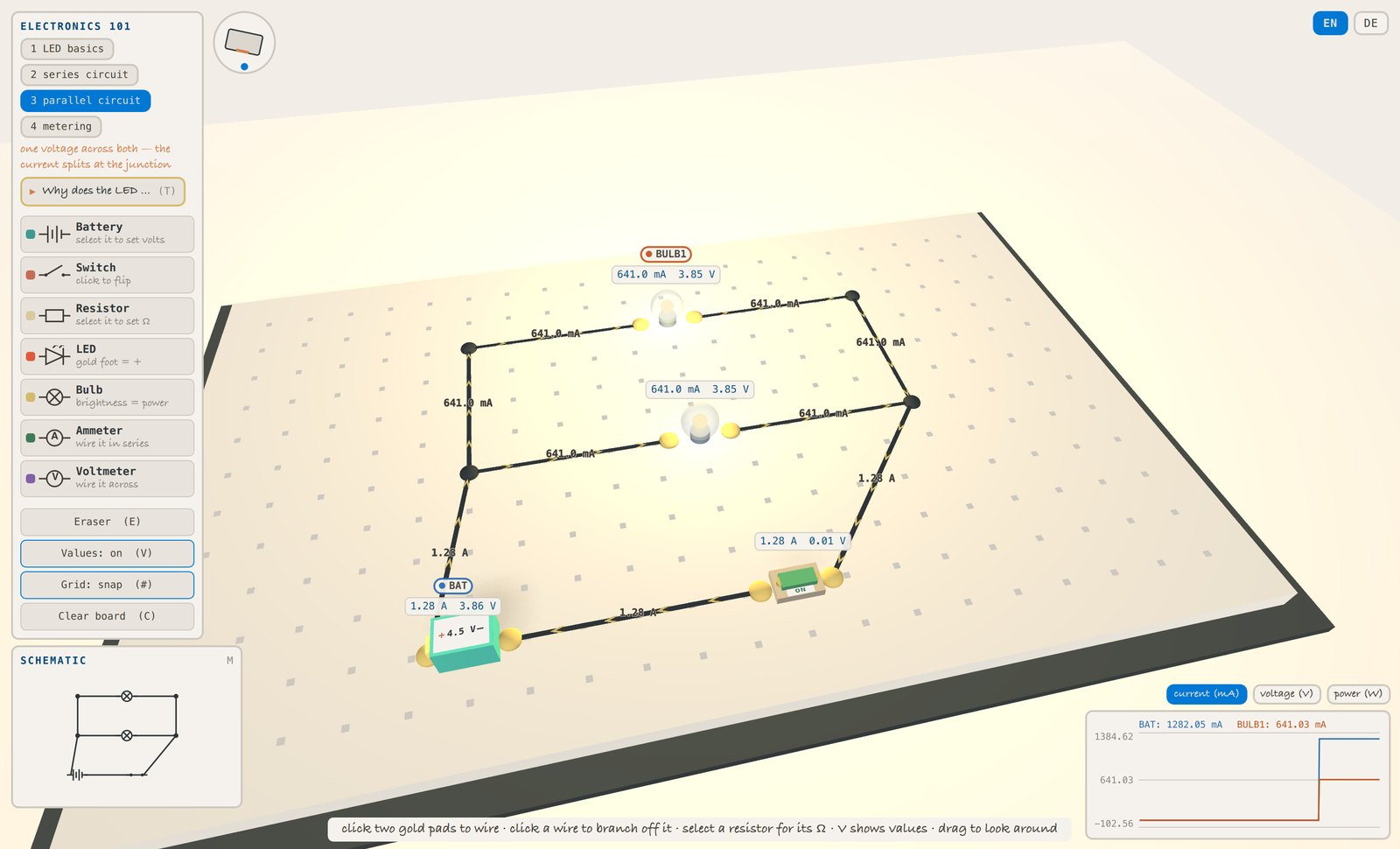
- parallel circuit — one voltage across both — the current splits at the junction
- metering — the ammeter sits IN the loop, the voltmeter ACROSS the part
- transistor — 0.8 mA into the base commands the 9.8 mA through the lamp — and the part would pass a hundred times its base current if the lamp asked
- diode OR — either input lights the lamp — and the diodes are what keep the two inputs from driving each other
- AND gate — two transistors in SERIES: the current must get past both, so both inputs have to be on
- OR gate — the same two in PARALLEL: either path on its own is enough
- XOR gate — exactly one — (A or B) and not (A and B), and that costs five transistors
- logic gate — one chip, six functions: select it and switch what it does — the package, the symbol and the table all follow. Unwire VCC and it stops answering
- half adder — two gates reading the same two inputs: SUM is A xor B, CARRY is A and B — which is binary addition, and the first thing gates were ever built for
Running it
Labs run in the Dojo from a Clayground checkout:
cmake -B build && cmake --build build
./build/bin/claydojo --sbx labs/electronics-101/Sandbox.qml
Press ? inside any lab for its key map, and T where a guided tour is offered.